|
eLooM for STM32 application
v3.3.0
A framework for multitasking low power embedded applications powerd by STM32
|
|
eLooM for STM32 application
v3.3.0
A framework for multitasking low power embedded applications powerd by STM32
|
The framework as been designed for embedded low power applications powered by STM32 with the purpose of:
The design started with the analysis of many embedded applications. We can image the firmware as a set of concurrent tasks, where each task uses one or more services that, in turn, use one or more drivers. In this way a task export one or more features of the application.

The above image leads us to the final idea: the framework manages a set of tasks (we called it Managed Task) defined by the application, in order to implements the following features:
We focused on a design pattern that allow us to split the generic algorithms, that we need to implement the features described in the previous section, from the application specific data. This is done by introducing a special task, the INIT task, that is the first task to start and the one with the highest priority. It interacts with three other objects as displayed in Fig.21:
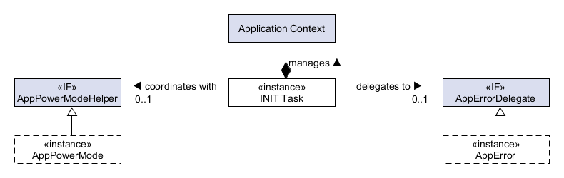
This three objects are grouped together in a private structure of type System and there is only one instance - s_xTheSystem - that is not directly accessible by the application.
While this is a very important part of the framework, Fig.1 displays the whole firmware architecture: a soft real-time multitasking system designed in multiple layers.

After the reset the system must be initialized in order to perform the normal operation. This is done in different steps. At the beginning the SysInit() is executed. This function is in charge of to perform the early initialization of the hardware:
Part of this initialization code is provided by the standard functions HAL_Init() and SystemClock_Config(). At this point the scheduler (FreeRTOS or ThreadX) is started and the control pass to the INIT task that is, with the IDLE task and the Timer Service Daemon task, the only available task and the one with the highest priority. The INIT task is in charge of to complete the system initialization before entering its commands loop.
A multitasking system is defined by one or more user defined application tasks that implement the application features. The framework abstracts this concept in the ApplicationContext class, that is a set of task objects implementing the AManagedTask abstract class or one of the its subclass. Each application task must implements the the AManagedTask interface, and so it defines a common API between the application tasks and the system. It is through this interface that the INIT task manages the application tasks.
Before allocating the ApplicationContext, the INIT task allocate and initialize the other two objects (see Fig.21), the Application Power Mode Helper and the Application Error Delegate. in this way the Managed Tasks can use all the services provided by by the framework.
The INIT task allocates the ApplicationContext and then it calls the SysLoadApplicationContext() function to allows the application to add the its Managed Tasks to the ApplicationContext. This function is defined as weak in the framework and the application must define its own implementation. In a typical example this function is defined in the App.c file.
After the SysLoadApplicationContext() is executed the INIT task is aware of all application tasks and it can continue with the system initialization. The next step is to complete the hardware initialization. For each AManagedTask the INIT task calls the AMTHardwareInit() function. This function is overloaded and used by an application task object in order to initialize the task specific hardware.
At this moment the hardware of the MCU is initialized, all the peripherals are ready to be used, but usually they are not started yet. This will be done later in the application task control loop or in the AMTOnEnterTaskControlLoop() function, after the task creation.
The next step in the initialization process is to create and initialize the software resources used by the application tasks. Once again the INIT task iterates between the AManagedTask and it calls the function AMTOnCreateTask(). This function is overloaded and used by an application task object in order to initialize the task specific software resources and to provide to the INIT task all the parameters needed to instantiate a native RTOS task. These parameters include:
At this point the system is almost initialized and ready to run: all the drivers are initialized, all the application task objects are ready. Before giving the control to the application tasks, the INIT task calls the weak function SysOnStartApplication(). This optional function can be defined by the application in order to make other initialization stuff after all application task objects have been initialized, and before the system runs. This process is displayed in the sequence diagram of Fig.2.
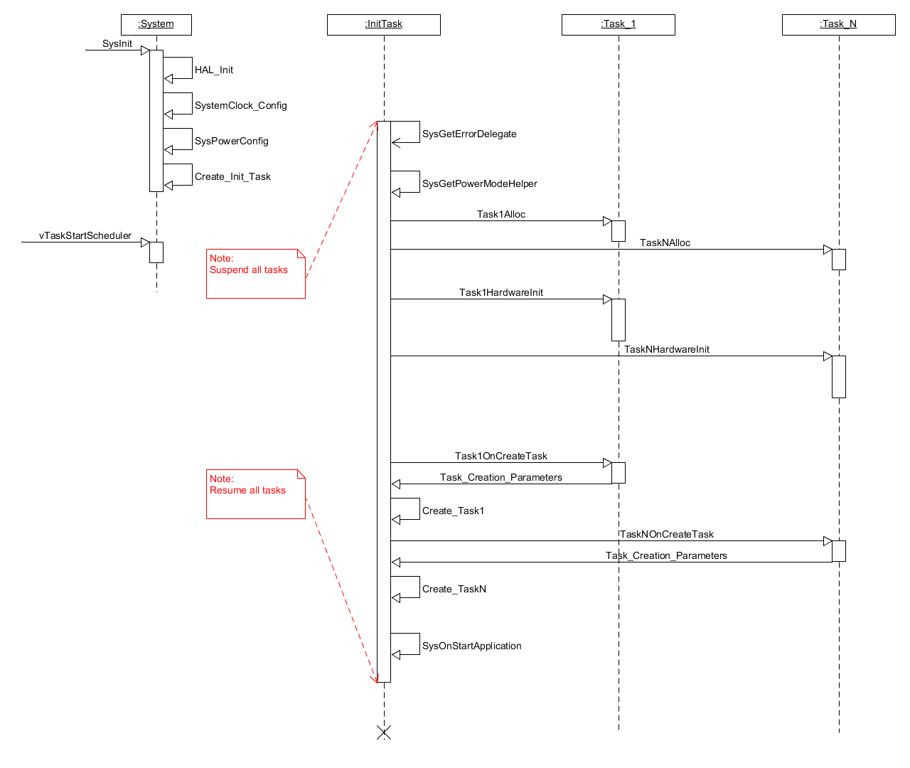
Note: the startup process described in this section is, usually, done in few ms.
After the system initialization is done, the INIT task gives the control to the application tasks, and it enters a command loop. In this loop the INIT task is suspended waiting for a system command invoked by other tasks or Interrupt Service Routine (ISR). An example of system command is the power management command that can be used by the application through the SysPostPowerModeEvent() function. This function sends a power mode event to the INIT task. The INIT task manages the event, and in case it does switch the system to a different power mode. Another type of command is the error command. The application uses the function SysPostErrorEvent() to notify the system when an error occurs. We will see later that the error management is done in two steps, the error notification first, and then the error recovery.
It is important to note that, while the framework defines the API and the syntax of a SysEvent, the actual value of the event is defined by the application. This design choice, used also for the power mode state machine implementation, gives flexibility because each application has its own characteristics.
A low power application should take advantage of many way to reduce the power consumption thanks to the STM32 low power mode. The main idea is to put the MCU core in low power mode and to stop the peripherals clock as soon as possible.
But every application has its own characteristics and different requirements, and this can be modeled using a state machine where:
To implement the power mode state machine, the INIT task interacts with the application provided Power Mode Helper object, that implements the IAppPowerModeHelper interface.
The framework provides a default implementation of the Power Mode Helper interface that is the SysDefPowerModeHelper. The application can provides its own object by defining the weak function SysGetPowerModeHelper(). The default implementation defines a state machine with 2 states RUN and SLEEP_1. It is displayed in Fig.5 with the possible transactions, the events that trigger each transaction, and the power policy of each state.
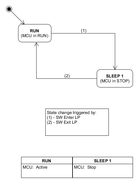
In SLEEP_1 mode the power consumption is reduced thanks to the following actions:
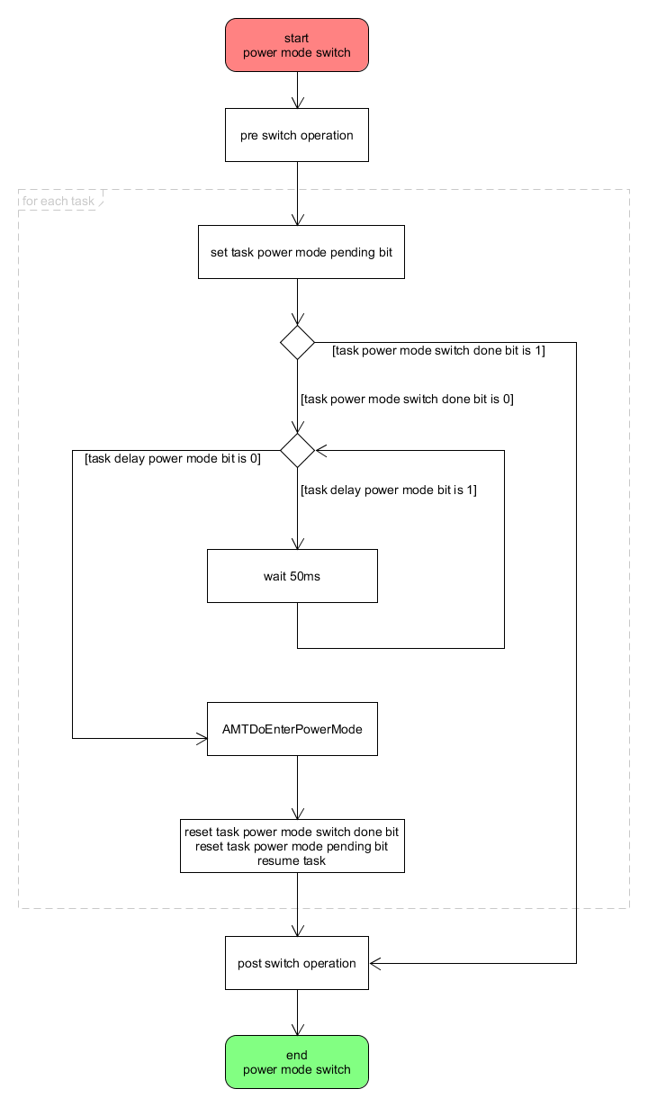
Before entering a power mode all application tasks must be in a safe state: for example all driver operations should be completed, a task should complete one step of its control loop, etc. This is a three steps process as displayed in Fig.12:

As discussed in the section INIT task command loop the INIT task is responsible to put the system in a specified power mode. When it receives a power mode related SysEvent it takes the control over the system. The first step is to check with the APMH if a power mode transaction is needed. Two virtual function defined by the APMH are used:
In case the INIT task starts the transaction to a new power mode, it first notifies the AManagedTask that a new transaction is going to start by calling the virtual function AMTExOnEnterPowerMode(). By overriding this method an application managed task can perform some action just before there transaction start. Normally these actions should be very short in order to keep the overall execution time of the power mode transaction as short as possible. As consequence, the system will feel more responsive.
Then the INIT task signals the application tasks the beginning of the power mode transaction by setting the nPowerModeSwitchPending bit of the task AManagedTask::m_xStatus flag, then it forwards the request to the application tasks using the AMTDoEnterPowerMode() function, after checking the nDelayPowerModeSwitch of the AManagedTask::m_xStatus flag. This flag is set by an application task to delay the power mode switch. It is responsibility of the AManagedTask to check the nPowerModeSwitchPending bit of the AManagedTask::m_xStatus flag and reset the nDelayPowerModeSwitch bit when it has finished the current operation. This is implemented in the default control loop AMTRun(). Note that a managed task subclass does not need to worry about this implementation of the PM transaction, but it can focus on its own logic to reconfigure itself and, eventually, its low level driver by overriding the AMTDoEnterPowerMode(). The framework will call that entry point at the right moment. The behavior of the INIT task is summarized in the following flow chart.
The control loop of the application tasks has to be implemented by taking into account the power management requirement of the system. Each task must contribute to the power efficiency of the system. The flow chart in Fig.8 display a generic implementation.
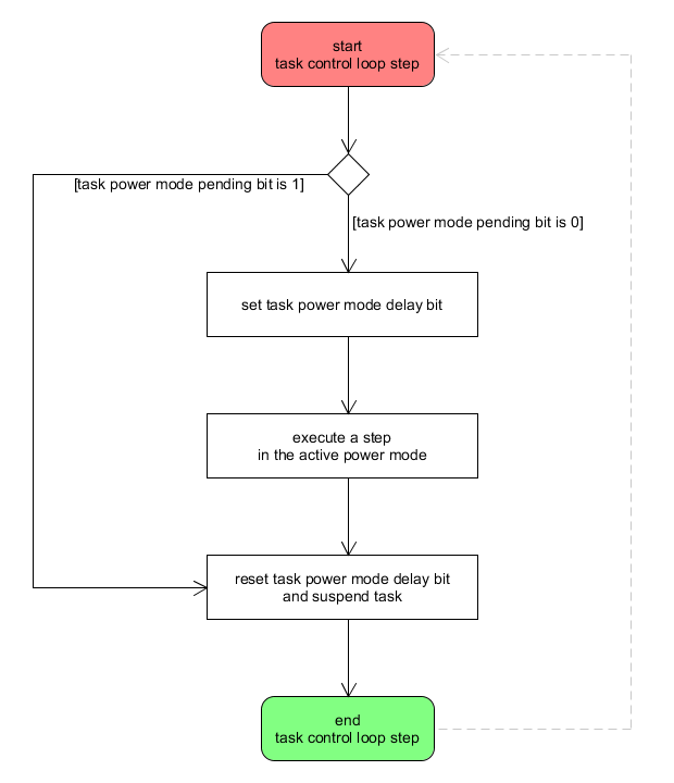
At the beginning of the control loop, the task checks if there is a power mode switch pending request (AManagedTask::m_xStatus nPowerModeSwitchPending). In this case the task resets its power mode delay switch bit (AManagedTask::m_xStatus nDelayPowerModeSwitch) and it suspends itself waiting for the INIT task to complete the power mode switch. Otherwise (AManagedTask::m_xStatus nPowerModeSwitchPending == 0) the task set the power mode delay switch bit (AManagedTask::m_xStatus nDelayPowerModeSwitch = 1), then it executes a step according to the active power mode, and, at the end of the step, it resets the power mode delay switch bit (AManagedTask::m_xStatus nDelayPowerModeSwitch = 0).
In a complex multitasking application, there can be dependencies between application tasks. This can be an issue during the a power mode transaction. Imagine that a task Ta depends on a task Tb. If Tb executes the PM transaction before Ta, then Ta could not work properly. For example it needs a service provide by Tb during its step execution, but Tb is suspended because it already did the PM transaction.
The framework provides a generic way to manage this issue. It defines three PM classes for a AManagedTaskEx:
An object of type AManagedTask belongs to E_PM_CLASS_0. The application can modify the PM class of an AManagedTaskEx by using the method AMTExSetPMClass(). This can be done once, for example during the task initialization (e.g. AMTOnCreateTask()) or also just before the PM transaction in the method AMTExOnEnterPowerMode(). This feature provides the capability to configure the PM class for each task depending on the current PM transaction. When the INIT task executes a transaction to a new PM state, it will switch first all managed tasks belonging to E_PM_CLASS_0, then the managed task belonging to E_PM_CLASS_1 and, at the end, the managed task belonging to E_PM_CLASS_2.
Some others things are used in order to reduce the current consumption. During the system initialization the clock three must be configured according to the application requirement. We can use CubeMX for this purpose and copy&paste the generated SystemClock_Config() function in the [APP_ROOT]/mx/Src/sysinit_mx.c file. SystemPower_Config() is defined in the same file and it configures all not used pin of the MCU in analog input mode. It must be modified by the developer.
The system tracks the last error occurred in the Service Level layer and in the Low Level layer using a global 32 bits variable g_nSysError and a set of convenient macro to operate it. The macro are defined in the syserror.h file. The application can defines its own error code in the apperror.h file starting from the value APP_BASE_ERROR_CODE. The generic and simple error support is completed by the function sys_error_handler() that, at the moment, blocks the calling task, but it can be redefined by the application.
In order to integrate the simple error support, the system provides a more structured, powerful and flexible design pattern to manage the errors. It is based on some interface as displayed in Fig.10

During the system initialization, the INIT task calls the SysGetErrorDelegate() function in order to get a pointer to an object that implement the IApplicationErrorDelegate interface. The function is defined as weak so the application can provide its own errors manager delegate. The default Application Error Delegate (AED) does nothing, so the advanced error framework is disabled. The AED is initialized - IAEDInit() - before the application context when the application managed tasks are created. This allows the application tasks to use the services provided by the AED during the initialization. In particular, if a task need to handle a critical error, it can implement the IErrFirstResponder interface and register itself as an error first responder - IAEDAddFirstResponder() - of the AED. The first responders are objects activated as soon an error is detected. Fig.11 displays how this error framework is integrated in the INIT control loop.

When the system receives an event (1), it checks if it is a power mode event or an error event. In the latter case (2) the system notifies the AED before adding the event in the system event queue (4). The AED immediately forward the event to the first responder objects. This allows a quick reaction of the system to a critical error. To be effective, the first responder action should be quick and, moreover, the number of first responders are limited to IAEDGetMaxFirstResponderPriority(). The first responder objects are activated from the one with highest priority, that is 0, to the one with the lowest priority. When the error event is asynchronously fetched from the system queue by the INIT task, it delegates the AEM to process the event (5). In this way the power mode loop is split from the error management loop. It is responsibility of the AEM to handle the error and to forward it to all application managed tasks (6). An application managed task receive an error event by implementing the AMTHandleError() function.
The AED is usually implemented by an AppErrorManager class (AEM). This class, other then implementing the IApplicationErrorDelegate interface, uses the STM32 System Watchdog peripheral (WDG) to automatically reset the system when an unexpected error occurs. The WWGD ISR generate a system error event with an application specific period in order to check if all managed tasks are still running. A managed task must call the AMTNotifyIsStillRunning() periodically to inform the system that it is working fine and prevent a system reset. This is usually done in the task control loop at the end of each step if no error is reported from the step execution. If a managed task has to do a long-lasting operation, then it should call the AMTResetAEDCounter() in order to delay the WWDG reset.
eLooM introduces modularity and makes complex firmware easy to port to different board and different MCU families. In a well designd eLooM applicatoin the code at Application Layer, Services Layer or the extensions to the Event layer is portable with zero or very few effort. Most of the effort is required at Low Level API to configure the peripheral drivers for the new board.

eLooM takes advantage of the configuration and code generation capabilities of STM32CubeMX. In Fig.13, the application provided part, MX driver, contains the HAL initializatoin code generated by STM32CubeMX. In fact, in an eLooM project there is a folder named mx as displayed in Fig.14
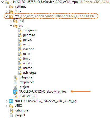
Inside this folder there is the .ioc project file (NUCLEO-U575ZI-Q_eLooM_prj.ioc in the above example) that a developer can use to modify the IP configuration, and update the code. Not everything is automatic. The files mx.h and mx.c are not generated by STM32CubeMX, but they must be mantained by the developer. Those files define the structure containing the configuration parameters for each IP used in the application. They are linked to a managed task that control a specific subsystem, for example during the ApplicationContext definition:
A managed task only stores a reference to an MX configuration structure, and it will pass the reference to the low level IDriver in the hardware initialization virtual function AMTHardwareInit(). For example this is the code for the spI2C1BusObj:
in the above example p_obj->p_mx_drv_cfg is the same reference, &MX_I2C1InitParams, passed in the task allocation spI2C1BusObj = I2CBusTaskAlloc(&MX_I2C1InitParams);.
In an embedded application a developer must manage asynchronous request coming from MCU peripherals or external component connected to one or more pin of the MCU. These are the Interrupt requests (IRQ). The HAL driver provides a simple, generic multi-instance and feature-oriented set of procedural APIs that simplify the user application implementation. The HAL driver source code is developed in Strict ANSI-C. For the IRQ, the HAL peripheral drivers include interrupt handle and user callback functions. For example, these are the prototype of the interrupt handler for the I2C and EXTI peripherals with the respective callbacks:
eLooM, following the Object Oriented programming model, provides a set of interface and objects that can be used and extended, like managed task (AManagedTask) and low level driver (IDriver). An embedded applicaiton is designed as a set of managed task, each of which is the gatekeeper for one or more hardware peripherals of the MCU. For example an application defined I2CTask object can be the gatekeeper for an I2C instance of the MCU. This means that we must be able to activate a specific I2CTask object from the HAL I2C callbacks.

How to link an IRQ callback to an object? eLooM provides two class to support this scenario:
In the I2C example, the HWDriverMap_t can be added in the class object of the I2CMasterDriver because in OO we model it as a static member of the the I2CMasterDriver class.
Note: a static class member is a member that is not bound to a specific instance of the class, but the only one copy of the data is maintained and accessible for all objects of the class.
The link between the object and the callback is done in the virtual function IDrvInit():
Now, from the I2C IRQ callback we can use the class object to access the map and the right I2CMasterDriver istance:
The sequence diagram of Fig.16 summarizes what we saw in the previous code fragmants.

The MTMap_t can be used in the same way to link a IRQ callback with a managed task.
Since v3.2.0 eLooM supports FreeRTOS and ThreadX as RTOS in the Kernel layer, see Fig.1. In fact, there are two version of eLooM, one for each RTOS. This is because one of the main goal of eLooM is to have optimized code to reach the best performance on STM32, as discussed in this article. We don't want to make compromise between FreeRTOS and ThreadX. We discovered also that this choice has a very little impact on code portability thanks to the similar semantic of the API provided by the two schedulers: porting a complex eLooM application from one RTOS to the other requires few hours effort.
Nonetheless, there are few things in eLooM designed to simplify the development, in term of portability between FreeRTOS and ThreadX. Both ROTS provide API for:
eLooM provides a framework level API for dynamic memory management and critical sections. These API are exported in different header file, so an application file can include only the required services:
These API help a developer to write code that works on both implementation of eLooM as it is, or easier to port. At the same time these services do not hide the native implementations provided by the RTOS, but they are just another option for the developer
Since version v3.3.0 the above concepts have been generalized. We identified a minimum set of basic features that work on top of the kernel layer and that are used at all levels of the framework. These are, other that the critical section and the dynamic memory management:
So, we introduced in this version of eLooM a new umbrella header file named eloom_sysbase.h that simplifies the include chain across the framework and the eLooM Components. It can be used also at application level in case of a new class that does not inherit from the framework hierarchy.